|
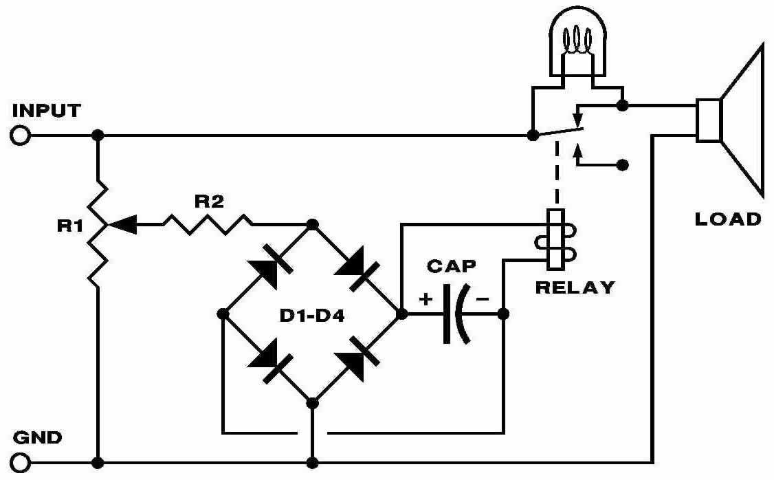
Free spreadsheet comparison of computer hard disc recording with analog tape recording spreadsheet Free musical PITCH vs. FREQUENCY & WAVE LENGTH spreadsheet (Microsoft Excel file) Free woofer box tuning program ( T.exe ) (pop-up DOS window operates from the Windows desktop) Free Excel spreadsheet of JBL drivers, their parameters, and included active cells that design boxes for them. AUTOMATIC LOUDSPEAKER PROTECTOR CIRCUIT I've used these nifty protectors often a dozen at a time, on three-way systems with subs in high-volume control rooms and in touring sound systems designed for rental use. Variations on the circuit below can protect valuable drivers without changing the sound of your speakers the way fuses or light bulbs do, and maybe even get the message across that the "talent" is playing the monitor system too friggin' loud. The cut-off level of the circuit may be set to an absolute voltage to protect drivers from destruction, or with the aid of a sound level meter, to a maximum volume level safe for protection against hearing loss. For multi-way speaker systems, the cut off setting should be done for each driver, so that a particular driver cuts off depending on power in its frequency range. I strongly recommend pink noise as a test signal for level setting, though if you have wimpy tweeters or beryllium diaphragms, you may want to use white noise for an extra measure of safety. Warning: the max-power setting is much easier to sell to the client than the hearing-safe setting. For subwoofers, relay contacts need to be around 50-100 amps rated, with big, heavy 24 volt coils. For tweeters, a 1 to
3-amp rating will do the trick, but the coil may be no more than 6 volts.
Relay contact ratings should be on the order of the current expected, not grossly over rated. R1 is normally 100-500 ohms wire wound, and the relay coil voltage is normally around half of the expected overload voltage. R2 prevents direct connection of the diode bridge to the power amplifier. Larger caps will cause the circuit to interrupt for longer times, smaller caps for shorter times—all the way down to a chatter. Some parts value trial and error will normally be needed depending on the voltage you need at protect interrupt, but if you find you have to turn the pot nearly all the way up, try a lower voltage relay coil. This circuit is intended for techs who can use it confidently. No support is available. |